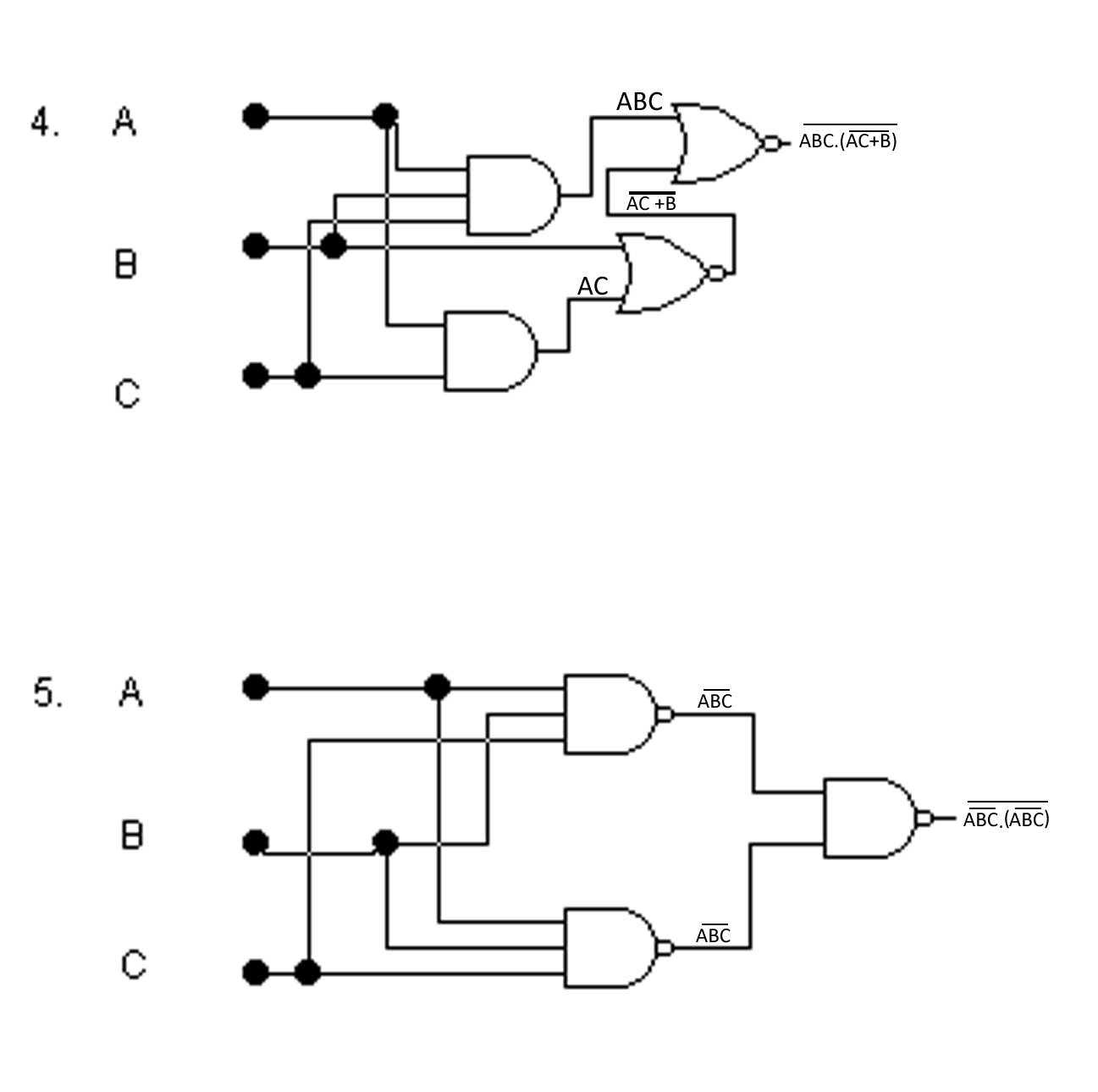
A Logic Gate Circuit
Xor gate logic diagram / xor gate logic diagram Logic remains similarly respectively glows Xor nand xnor logic nor vhdl simulate input engineersgarage verify dummies wiring inverter scosche inputs
Logic Gates - Inst Tools
The diagram of the logic gate circuit is given below. the output y of Vhdl tutorial – 5: design, simulate and verify nand, nor, xor and xnor Digital breadboard system logic gates circuits integrated electronics
Logic circuit gate gates examples study basic ten
Logic gate circuit ~ study with prandanaLogic gates and logic circuits Logic gatesLogic gates truth table circuits digital blocks part small gate building other why nuts volts.
Circuit logic equivalent gates gate switch relay connected function instrumentationtools normally parallel open contacts lamp because control will energize actuatedXor wiring Integrated circuitsIc logic integrated circuits gate gates inside electronics ics pinout basic simple dip package shift sparkfun most common these soic.

Gate transistor logic gates input transistors truth table inputs digital simple circuit output electronics circuits resistor structure open diagram using
Gate cdot representedLogic gate circuit ~ study with prandana Digital electronics: logic gatesGate logic circuit study.
Small logic gates — the building blocks of digital circuitsTruth tables & circuit diagrams of logic gates Logic gates gate circuits diy nand basic verilog microchip starting electrical stack buffers source original components exampleDigital logic gate full cheat sheet.

Gate logic diagram digital table cheat sheet inputs multiplication consider operation simply
Digital logic .
.


logic gate circuit ~ Study with Prandana

logic gate circuit ~ Study with Prandana

The diagram of the logic gate circuit is given below. The output Y of

Integrated Circuits - SparkFun Learn

Small Logic Gates — The building blocks of digital circuits - Part 2

Xor Gate Logic Diagram / Xor Gate Logic Diagram - Wiring Diagram

Digital Logic Gate Full Cheat Sheet

digital logic - AND gate output when inputs are open - Electrical

VHDL Tutorial – 5: Design, simulate and verify NAND, NOR, XOR and XNOR