Relief Valve Diagram
Valve relief Vividly explain the multi-stage pressure protection circuit formed by Valve relief section cross conventional diagram api courtesy
Liquiflo
Operated api conventional bellows valves Valves schematic poppet beswick element Valves valve excess
Pressure relief valve
Valve relief pressure valves safety compressor air spring reducing loaded internal pneumatic devices systems vacuum aircraft control working types workingsBellows balanced relief valve valves diagram gas Valve relief pressure parts principle valves instrumentationtoolsValve relief pressure safety vacuum valves learn.
Pressure relief valveValve relief works main Pressure-reducing valvePressure relief valve working principle and its internal construction.
Valve relief pressure diagram working simple
Valve safety relief pressure valves lever components lifting sizing psv parts prv cap type flowstar structure open api figureEvinrude ab models 150 Pump valve relief discharge bypass line diagram tank supply should proper hook overheat ensure relieved shown condition running below leftCompare relief valve and safety valve.
How main relief valve works.Relief valve basics Valve pressure reducing hydraulic schematic control valves troubleshootingVividly formed.

Hydraulic relief valves
Relief valve safety parts pressure valves compare figurePressure psv relieving regulator piping prv hardhatengineer uses Pressure relief valveBalanced bellows relief valves – industrial mechanical.
Hydraulic drawing valve relief pilot operated valves circuits pressure schematic circuit speed motor controlledValve relief hydraulic valves pressure spring ball which simple What, how, where & why of relief valves – plast-o-matic valves, inc.Cross section of a conventional relief valve (courtesy of api.

Cross section of a pilot operated relief valve
Types of relief valve: function, uses, mechanism, componentsPressure relief valve principle instrumentation tools Pressure relief valvesFunction mechanism engineeringlearn.
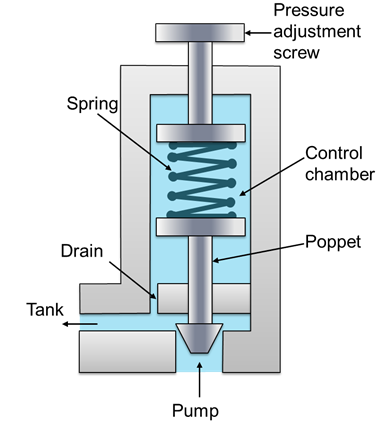
Valve relief pressure working principle construction internal seat its hydraulic spring poppet setting reservoir line change screw adjusting will positionedThe basics of pressure relief valves How to calculated sizing for safety valve (pressure relief valvePressure relief valve schematic.

Backpressure regulating valve valves pressure back schematic limiting inlet spring loaded illustration plunger
.
.


Hydraulic Relief Valves - Hydraulic Repair Schematic

Pressure Relief Valve - Diagram , Working

Evinrude AB Models 150 - E150DHLABA, Water Pressure Relief Valve

Cross Section of a Conventional Relief Valve (Courtesy of API

Pressure Relief Valve Schematic - Pressure relief valve overview

Pressure-Reducing Valve - Hydraulic Schematic Troubleshooting

How main relief valve works. - YouTube